 |
China Sales and Service Office: Contact: Alan Cao (曹全喜) Tel: +86-131 2475 3246 Email: cquanxi@163.com |
| Home | QE / IPCE / SR Measurements | I-V Measurements | I-V System Health | Services | About |
QEX12M Solar Module Quantum Efficiency Spectral Response Measurement System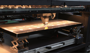 PV Measurements is proud to introduce the QEX12M Photovoltaic Module Quantum Efficiency Measurement System. The QEX12M Photovoltaic Module Quantum Efficiency / Spectral Response Measurement System empowers researchers, quality engineers, and manufacturing managers to explore new dimensions in their photovoltaic devices. ♦ Turn-key solution for photovoltaic module analysis ♦ Non-destructive cell measurements ♦ True module measurements for spectral mismatch corrections ♦ 150 mA current protection for experimental modules Reflective Optical PathThere are no refractive focusing optics in the main beam path of the QEX12M. This avoids chromatic aberrations, enabling the probe beam size to be uniform at all wavelengths. This ensures that any measured features represent bona-fide characteristics of the device, not artifacts such as grid lines, device boundaries or other device non-uniformities near the probe beam.Monitor PhotodiodeThe intensity of any light source will vary with time. The QEX12M performs simultaneous measurements of the device signal strength and the probe light intensity, minimizing the noise contribution of lamp intensity variations in measurement results.CalibrationThe system includes a reference photodiode that is calibrated for spectral response and traceable to NIST. A simple scan of the reference photodiode calibrates the QEX12M Quantum Efficiency System’s optical path and measurement electronics.Wavelength Range & UncertaintyThe basic system wavelength range is 300 nm to 1100 nm. Typical repeatability for c-Si modules is better than ± 1 % in the 400 nm to 1000 nm range and better than ± 2 % in the 300 nm to 400 nm and 1000 nm to 1100 nm ranges. The default beam spectral bandwidth is approximately 10 nm; narrower or wider bandwidths can be obtained by adjusting the monochromator slits. The measurement interval is selectable with a default of 10 nm. Optional wavelength range extensions to 1400 nm and 1800 nm ensure that the full range of module response is within reach.Monochromatic Light ModulationThe QEX12M uses an adjustable mechanical chopper to modulate the light at rates between 4 Hz and 200 Hz. Solar cells with long response times require slower chopping speeds for accurate measurements, whereas faster devices can be measured more quickly with higher chopping speeds.Spot Bias LightBias light is an important feature in a QE system because some device types exhibit different characteristics depending on the incident light intensity. The QEX12M illuminates a region on the sample approximately 1.5 cm in diameter with stable, broad-band bias light adjustable from 0 to 1 sun intensity to simulate intended end-use operating conditions. The included holder for 25 mm diameter optics enables the use of optical filters to customize the bias light spectrum. PV Measurements also offers accessories to facilitate application of spectrally-selective bias light.Test Fixtures for Individual CellsThe QEX12M can measure a wide variety of individual solar cells in addition to full modules. The system includes a platform for the mounting of solar panels, but since no single test fixture design is suitable for all cell types, a solar cell test fixture is not included. Please order one if you expect to measure solar cells in the QEX12M. PV Measurements offers a variety of vacuum and clamp test fixtures to hold and contact test devices. Temperature control capability up to 125 °C is an option for some test fixtures.Computer & SoftwareThe system operates automatically under the control of a computer with a Microsoft WindowsTM Operating System and custom measurement and analysis software. The system software controls the equipment, gathers the instrument readings, and maintains the calibration information. It provides a graphical user interface, allowing the operator to easily and quickly specify tests to be performed, monitor test progress, and produce clear and informative test reports. The software saves the data in tab-delimited text format for simple import to graphing or other data analysis software.Basic System Features♦ Measures PV modules up to 1 m x 2 m in size♦ Non-destructive measurements ♦ Voltage bias capability -5 V to +40 V ♦ 150 mA current protection for experimental modules ♦ User changeable monochromatic light spectral bandwidth ♦ Monochromatic probe light with 300 nm to 1100 nm wavelength range ♦ Selectable wavelength interval (default 10 nm) ♦ Dual grating monochromator with computer control ♦ Filter wheel with order-sorting and stray light attenuation filters ♦ Calibrated reference photodiode, NIST traceable (one step) ♦ Line filter for wavelength calibration verification ♦ Computer system with easy-to-use graphical user interface ♦ Data saved in text files for easy import into spreadsheets ♦ Simultaneous measurement of device signal and monochromatic light intensity ♦ White bias light source (up to 1 sun) with filter options at the measurement spot ♦ Broadband bias lighting for other cells ♦ Chopping speed 4 Hz to 200 Hz ♦ Calculates Jsc estimate with the AM1.5G, AM1.5D and AM0 reference spectra or spectra of your choice ♦ Complete scan in less than 1 minute for 12 wavelengths (minimum required for ASTM E 1021-06) ♦ Detailed scan with 10 nm step size from 300 nm to 1100 nm in under 6 minutes ♦ Setup and training at customer’s site ♦ Instruction manual ♦ Spare Lamps Defect CharacterizationThe QEX12M can be used to study failure modes in stressed modules. The electroluminescence image shows the loctations of defects in the solar module and the QE data is used for additional defect characterization. The EL image is acquired with an additional tool, not the QEX12M. Shunting of inline devices may make absolute QE measurements impractical but relative QE measurements can be obtained in most cases.Module Performance MeasurementsMeasure a module to be tested instead of a similar mini-module to ensure accurate spectral mismatch correction measurements.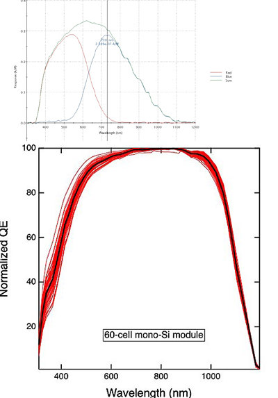 Digital Location ControlThe QEX12M uses a digital location control to ensure precision in the measurement location. This makes it easier to compare the same location before and after stressing of the module.Local ImagingThe integrated digital microscope enables accurate alignment of the probe beam and recording of the appearance of the solar cell in the vicinity of the measured spot.Customizable ConfigurationPlease contact us to learn more about available custom configurations of the module QE system.Options♦ 300 nm to 1400 nm spectral range♦ 300 nm to 1800 nm spectral range ♦ LED bias lights ♦ Accessories♦ Vacuum test fixture♦ Test fixture temperature control ♦ X – Y scanning for response mapping at any wavelength (coarse LBIC) ♦ Custom test fixture Facility RequirementsThe QEX12M requires four 115 VAC, 10 A or two 230 VAC, 10 A circuits at 50 Hz or 60 Hz (please specify voltage and frequency with your order). The minimum space required is 4.7 m x 3.7 m. The equipment is expected to operate in an environment with little dust, temperature between 20 °C and 27 °C, no organic vapors or corrosive fumes, and relative humidity < 60 %.Individual systems may vary in appearance,components, and features. |
| Call +86-131 2475 3246 or email cquanxi@163.com to discuss your photovoltaic characterization needs. | Request Quote |